Saturday, November 29, 2008
Tuesday, July 15, 2008
Easy stepper motor control with the Freescale MCZ33970

Freescale MCZ33970 Dual Gauge Driver IC
While prototyping an ambient-display project that I've been mulling over, I came across the Freescale MC(Z)33970 Dual Gauge driver IC. The part seemed interesting, so I ordered a sample and whipped up a small C library to use in conjunction with a perf-boarded USB Bit Whacker I had on my workbench. (An Arduino library is also available below)
The MC(Z)33970 is a neat little stepper motor driver specifically designed to control small, two-phase steppers for automotive instrumentation displays. I should immediately point out that this driver isn't designed for general purpose stepper control, like the Allegro A3967. It has relatively weak current drivers and is only designed to sweep a pointer for a total of 340-degrees; this means low torque and a limited range of motion.
While these limitations may seem annoying at first, they make sense given the niche these ICs are designed to fill. Besides, the MCZs have a number of other redeeming features, such as programmable sweep velocity, programmable acceleration and deceleration parameters, and automatic "Return to Zero (RTZ)" functionality, which make them great for creating analog displays.

MC33970 Datasheet
MCZ33970 C Library
MCZ33970 Arduino code
Modified UBW Firmware
UBW Python Scripts
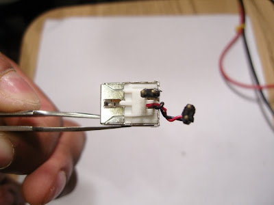
I didn't have any automotive displays about, but I did have a pair of Vexta steppers, so I decided to use them for this project.

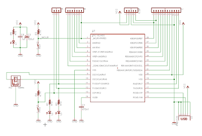
Interfacing schematic (Courtesy Freescale)
As you can see from the schematic, the connections are very straight-forward. The MCZ has built in protection diodes, so stepper windings can be connected directly to its pins. I couldn't find any optocouplers in my workshop so I connected the MCZ directly to my Bit Whacker. This is an EXTREMELY BAD idea, since the high-voltage stepper motor supply can potentially short to the digital supply if the IC fails. Since the Bit Whacker is conveniently connected to your USB port, this may lead to a very bad day. I *HIGHLY* recommend that you use optocouplers on the SPI lines in your design!
Moving on, to make wiring a bit easier I decided to move the SS pin over from RA5 to RB2. I'm pointing this out to those readers who may be scrutinizing my daughterboard photograph (absolutely none).

MCZ33970 Daughterboard
I epoxied the 24-pin SOICW IC to a perfboard, and with a few other parts, made a little daughterboard for a Bit Whacker.

USB Bit Whacker
- CM - Configure the stepper motor driver IC
- SM - Send a position update command to the driver IC

The completed assembly
Here is a video demonstrating the dual-drive and velocity control capability of the IC.
To make things slightly more interesting (very slight, indeed), I connected a Spectra Symbol SoftPot to one of the ADC pins of the Bit Whacker and used the readings to control the position of the stepper motor pointers. You can find the Python scripts above.
SoftPot stepper motor control

A bunch of pots
I can imagine a number of uses for this chip, especially in low-power ubiquitous computing devices. Things get really exciting when you have multiple ICs operating in concert. As I continue to burn through my summer-projects list, I'll see if I have time (or the need) for a MCZ-based Arduino shield. As always, if you find any bugs or need any help, please let me know.
Thanks,
Sumanth P.
Monday, June 23, 2008
Build a USB Bit Whacker in 10 minutes

I've moved! Please go here: http://bafoontecha.com/2008/06/23/build-a-usb-bit-whacker-in-10-minutes/ for the latest version of this article.
First, a bit of history... In the good-old days, computers came with these things called "parallel ports", or so I've been told (should that be active tense?) These "parallel ports", with a bit of register twiddling, empowered the user with 17-some-odd digital pins for inputting and outputting data. Newer computers computers tend to forgo parallel I/O methods for faster and sleeker I/O methods, ala, USB, USB, and USB. While these newer generation of I/O ports are much more compact and support higher bandwidths, they are a bit harder for the common user to interface with.
In comes the USB Bit Whacker. Calling the USB Bit Whacker a virtual parallel port is doing it a disservice; it's much, much more than that. It gives you complete control of a fairly powerful microcontroller, the PIC18F2550, through a serial, command-driven interface. The entire platform is powered from the USB bus, no wall-warts or additional wires! In addition, all communication occurs through a virtual serial (COM) port, using the USB CDC protocol.
Simple ASCII commands allow you to configure and use the following onboard hardware peripherals: SPI/I2C module, USART serial module, PWM module, and 13-channel 10-bit Analog-to-Digital converter module. Support for additional modules can easily be added to the open-source firmware.
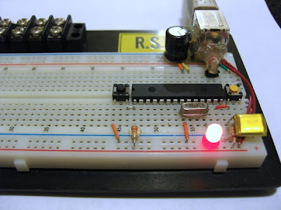
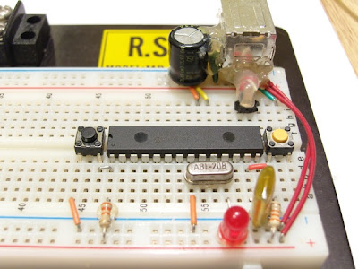
I love microcontrollers, and primarily due to the generosity of Microchip, have a number of PICs in my parts collection. I came across the USB Bit Whacker project while desperately trying to get USB CDC working on a PIC18F2550. Encouraged by the extreme simplicity of the schematic , I decided to breadboard it. In a matter of minutes, I had a working development kit. You can either buy a kit, or follow these instructions to build your own.
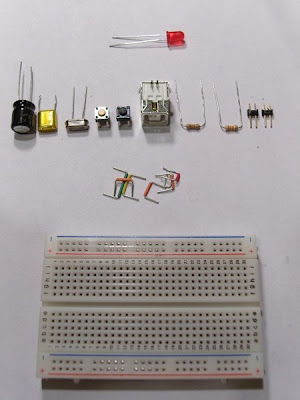
Requirements
- 220 uF electrolytic capacitor
- 0.1 uF capacitor
- 20 MHz oscillator (see the PIC18F2550 datasheet or additional options)
- 2 push buttons
- 1 USB Type B connector
- 2 3.3k resistors (the value of the pull-up resistor is not critical)
- 2 pieces of straight headers
- A few jumper wires
- A breadboard/perfboard
- 1 PIC18F2550 or PIC18f2450 microcontroller
- PIC Programmer
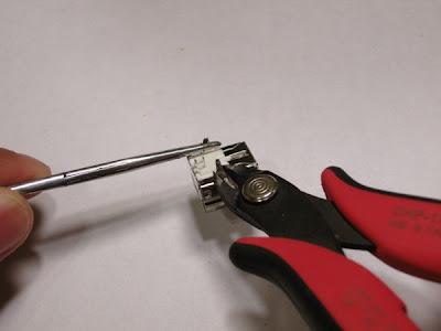
Hardware Construction
Prepare the USB connector by cutting off the mounting brackets
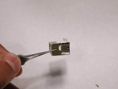
It should look something like this
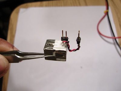
Solder the header pins to the USB connector.
Alternate view
Original schematic (Credit: Brian Schmalz)
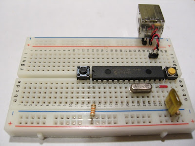
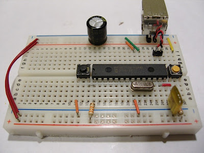
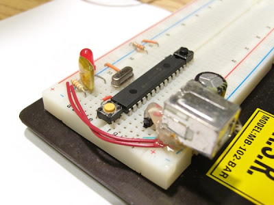
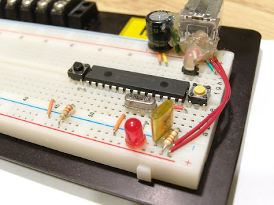
Begin placing the components on the breadboard
Completed breadboard USB Bit Whacker. (I left out the status LED)
Software
Now that you have a completed Bit Whacker, you need to burn the bootloader onto your PIC. Instructions for burning firmware onto your PIC are out of the scope of this document. Luckily, you can find a wealth of information online. I use an MPLAB ICD2 clone that I purchased on eBay.
If you are using a 20 MHz oscillator, you can use this bootloader firmware. Additional bootloader firmware is available on the USB Bit Whacker homepage (Search for 'Bootloader'). (I know this is confusing, but the *Bootloader* firmware is different than the USB Bit Whacker firmware. You need to burn the *Bootloader* firmware onto your PIC first using a dedicated PIC programmer. After this, additional firmware updates can be done through the USB port!)
Bit Whacker in Bootloader mode
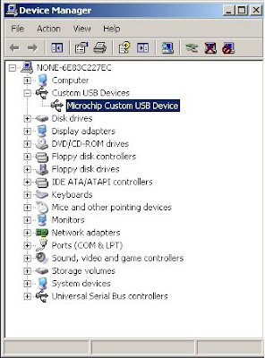
Once you've burned the Bootloader firmware onto your PIC18F2x50, you need to load the Bit Whacker firmware. Microchip provides a USB Framework, which comes with an application named PDFUSB.exe. Using PDFUSB, you can load Bit Whacker firmware onto your PIC. To prepare the PIC for loading firmware serially, you need to connect your development board to a USB port on your computer. Then, while holding down the "Program" button (the orange pushbutton in the picture above), press and release the "Reset" button (the black pushbutton in the picture above). The status LED on the prenatal USB Bit Whacker should be steady, and a Custom USB Device named "Microchip Custom USB Device" should show up in your Device Manager.
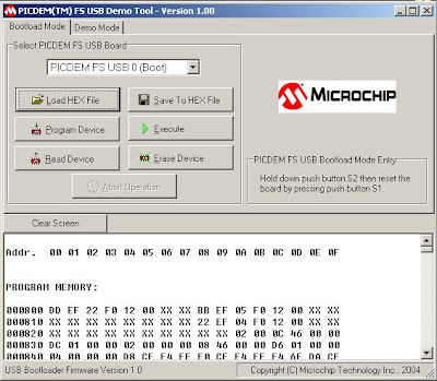
Download the latest USB Bit Whacker firmware, here. At the time of writing, this was v1.4.3. Load the PDFUSB.exe bootloader and select the firmware and the USB Board as follows:
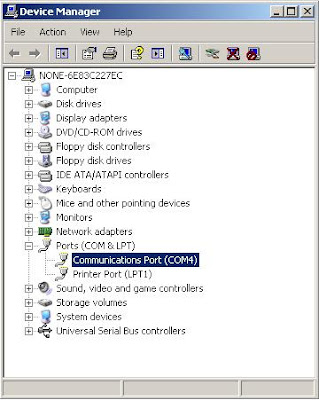
Click on "Program Device" to load the firmware onto the PIC. Once the loading is complete, hit "Execute" to switch to the USB Bit Whacker Firmware. The status LED on the breadboard should begin to blink. Looking in your Device Manager, you should have a new COM port. On my machine, this shows up as COM4.
Now, open you serial emulator of choice (HyperTerminal, teraterm, etc...) and open up the serial port. If you're using a Mac, try "screen /dev/tty.usbmodem1d11 57600".
Type the following commands to set Port A on the Bit Whacker to analog input, and to set a timer to output values of the analog pins at a 100ms interval (Unfortunately, you won't see what you are typing, so if you think you've made a mistake just hit "Enter" and try again. The next revision of the firmware should fix this. Also, this isn't as big a problem as it seems now, keep reading!)
c,31,0,0,5t,100,1
The first line calls the "Configure" command indicating that all five available pins on Port A are inputs, all the pins on Port B are outputs, all the pins on Port C are outputs, and the 5 Port A pins are analog inputs.
The second line calls the "Timer" command with an interval of 100 ms, in analog mode.
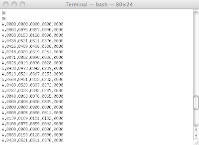
You should see a stream of 0's filling your terminal window. Try touching a few of the pins (2-7) to see the numbers change! You now have a rudimentary, but fairly powerful DAQ at your fingertips.
Term output
Further instructions on using your Bit Whacker can be found here.
Advanced Example
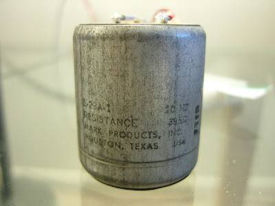
The major advantage of having a command-driven interface is that it is easily scriptable. I like to write small Python scripts to control my USB Bit Whacker. I had an old Geophone from EPO Depot laying around my parts bin. If you click the link, you can see that a Geophone is a simple electromagnetic device which generates a voltage based on the displacement of a magnetic mass. It's useful for detecting low-frequency vibrations such as earthquakes, footsteps, and in some cases, a combination of both.
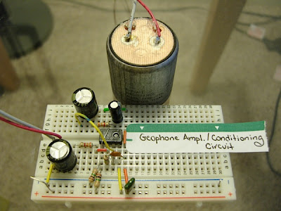
Scoping the output of the Geophone, I determined that the maximum voltage swing was around 4VPP (shaking it violently). The average VPP was around 100 mV. I wired up a quick op-amp circuit to center the Geophone output to 2.5V (1/2 the Bit Whacker rail voltage) and add a fair bit of amplification. I rely on the fact that the opamp can not exceed its supply rail voltage to protect the Bit Whacker inputs. This is generally not a good design practice, but hey, I was in a hurry.
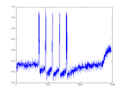
I then wrote a Python script to capture the analog output of the Geophone at a sampling rate of 200 Hz. Download it here.
Plot of captured footstep data
The plot above is of four footsteps near the Geophone. From the plot, I suspect the op-amp is latching up, but that's something I'll save for another post!
Additional Notes
I've made a number of Bit Whackers over the last few weeks and have made many modifications to the firmware, including adding SPI and I2C support. I've sent the changes to the developer, Brian Schmalz, who will hopefully roll them into the next firmware revision.
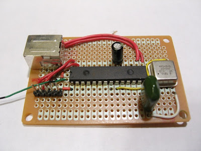
Here are a few pictures of the other Bit Whacker's that I've built. One way to prevent components from moving around is to hot-glue them.
Perf-board USB Bit Whacker
Thanks,
Sumanth P.
Powering your Technological Arts NanoCore C32 Development board
To help keep my series of articles on microcontroller development on Mac OS X concise, I've decided to spin-off somewhat tangential topics into their own posts. Here's mini-post on powering the Technological Arts NanoCore C32 development kit.


Jumper JB1
This Tech Arts development kit is compact and has relatively meager power requirements for a microcontroller board running at 24 MHz. In addition, the devkit uses a LM1086 Adjustable LDO Voltage Regulator and provides a jumper (JB1) to conveniently switch between 3.3V and 5.0V operation. I loaded up the basic "helloworld" example from Part 1, and measured the power consumption at both voltages with and without a serial cable connected:
- 3.3V, 16.7mA w/o serial port
- 3.3V, 68.0mA w/ serial port
- 5.0V, 17.6mA w/o serial port
- 5.0V, 76.2mA w/ serial port
Left/Top: 5.0V operation (JB1 open), Right/Bottom: 3.3V operation (JB1 closed)
While hacking code in the lab, using a wall-wart is fine, however, the low power requirements of this devkit give you a variety of options when taking your project on the road. I've powered my board using the following:
A standard AA battery pack provides around 6800 mAh - 12,000 mAh of battery life.
Alternate view
A generic 3.7V, 0.2W solar panel, which gives you a laaaarge number of mAh.
Remember to set jumper JB1!
Cell-phone battery packs are great sources of power. This is an
old Envoy 3.7V 900mAh Li-Ion cellphone battery pack I had lying around.
The usual warnings about Lithium-based rechargables apply!!!
Sunday, June 22, 2008
DIY right-angle headers
I often find the need to stick headers on my microcontroller projects, and I've come to prefer right-angle headers, as opposed to the traditional straight header, due to their unobtrusive, low-profile. Since right-angle headers are usually in low-supply, here's a couple of ways to make or acquire them from parts you probably have lying around. (The peripheral in the pictures is the LIS3LV02DQ 3-axis accelerometer)

We start with two pieces of straight header

We want the result to look something like this

Place the two straight headers at a right-angle, and tack solder each set of pins

Now, slide off the connecting plastic from one side. The pins may twist from side-to-side, don't worry.

The result should look something like this

Complete soldering pins to PCB. (I use a piece of scrap perf-board to make sure the pins point straight up)

The completed result.

Another angle.
Or...

Salvage headers from an old sound-card (Thanks, Purdue Surplus!)

Carefully, pull off the plastic connector

Apply a bit of flux to the pin pad

"Push" the pins through with a soldering iron

Flip the board over, and continue extracting the pins

Go make something!
Subscribe to:
Posts (Atom)